
I like to approach designing networks by starting with a solid foundation from the beginning. In my eyes, this mean utilizing network segmentation to its fullest. Intricate rule sets, host and network based protections, and real time threat detection all have their place, but architecting network segmentation in a protective manner sets the tone for everything else that is built on top of it. Today, I want to focus on a very easy but effective way to do this at the layer 2 level with VLANs and more specifically the granularity and protections that are granted by utilizing Private VLANs (PVLANs).
PVLANs take the segmentation regular VLANs create with their broadcast domains and allow you to further segment devices into three different port types or groups (Promiscuous, Isolated, and Community) with varying connection and protection profiles. PVLANs consist of both a primary and secondary VLAN. For example, in the below diagrams we utilize VLAN 100 as the primary VLAN and VLAN 200, 300, and 400 as the secondary VLANs. The primary VLAN is just like a regular 802.1q tagged VLAN and all PVLAN ports must be a member of it, thus making up the primary domain. It also has a secondary VLAN, which is used to identify community and isolated ports. Each unique secondary VLAN makes up the secondary sub domains. A key point is that while you can create multiple community secondary VLANs/subdomains per primary VLAN, you can only create one isolated secondary VLAN/subdomain per primary VLAN.
The three types of PVLAN ports are promiscuous, community, and isolated:
- Promiscuous ports are always associated with the primary VLAN. Promiscuous ports can communicate with all other ports in the PVLAN including the secondary VLANs. This is useful for devices that need to communicate with all devices in the PVLAN and this will be dependent on the purpose and scope of the devices residing in the PVLAN. There should always be at a minimum one promiscuous port in the PVLAN, that being the port connecting to the router/gateway for the PVLAN. In our examples below, VLAN 100 is the promiscuous VLAN.
- Community ports are used to segment devices that should be allowed to communicate with only other devices in the same community subdomain. You can create multiple community subdomains in the same PVLAN, but they will only be able to forward traffic to other devices in the same secondary VLAN, a promiscuous port, or a PVLAN trunk port. In the examples below, VLAN 300 and 400 are community VLANs. They can talk amongst themselves but not to each other.
- Isolated ports are used when you want to ensure that no other non-promiscuous ports can forward data to or receive traffic from a device. Of the three PVLAN port types, this is the most restrictive. In the examples below, this is VLAN 200.
Below we’ll look at a few high level examples of the various types of configurations you can see with PVLANs and the expected communications between them. The first however, is not a PVLAN example, but instead what you would normally expect with a regular VLAN configuration. You have a layer 2 switch that all hosts are connected to with an uplink to a firewall which is acting as the gateway for VLAN 100.
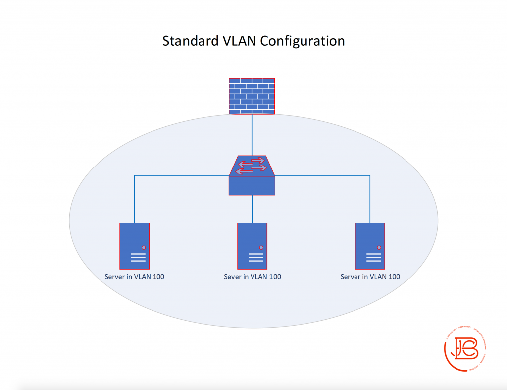
All servers in VLAN 100 can communicate with each other as long as there are no other ACL’s on the servers or switch. All servers can also communicate with their gateway on the firewall.
The first PVLAN configuration is depicting the same network, but now we have implemented PVLANs. A singe host (Server A) and the gateway are in the primary VLAN (VLAN 100) and have no secondary VLANs and are thus promiscuous ports. Server B and Server C are in a secondary VLAN (VLAN 200) which is configured as isolated. You’ll also notice that Server B and Server C state they are in VLAN 100, 200. This is to show that they are a member in the primary VLAN 100 and the secondary VLAN 200.
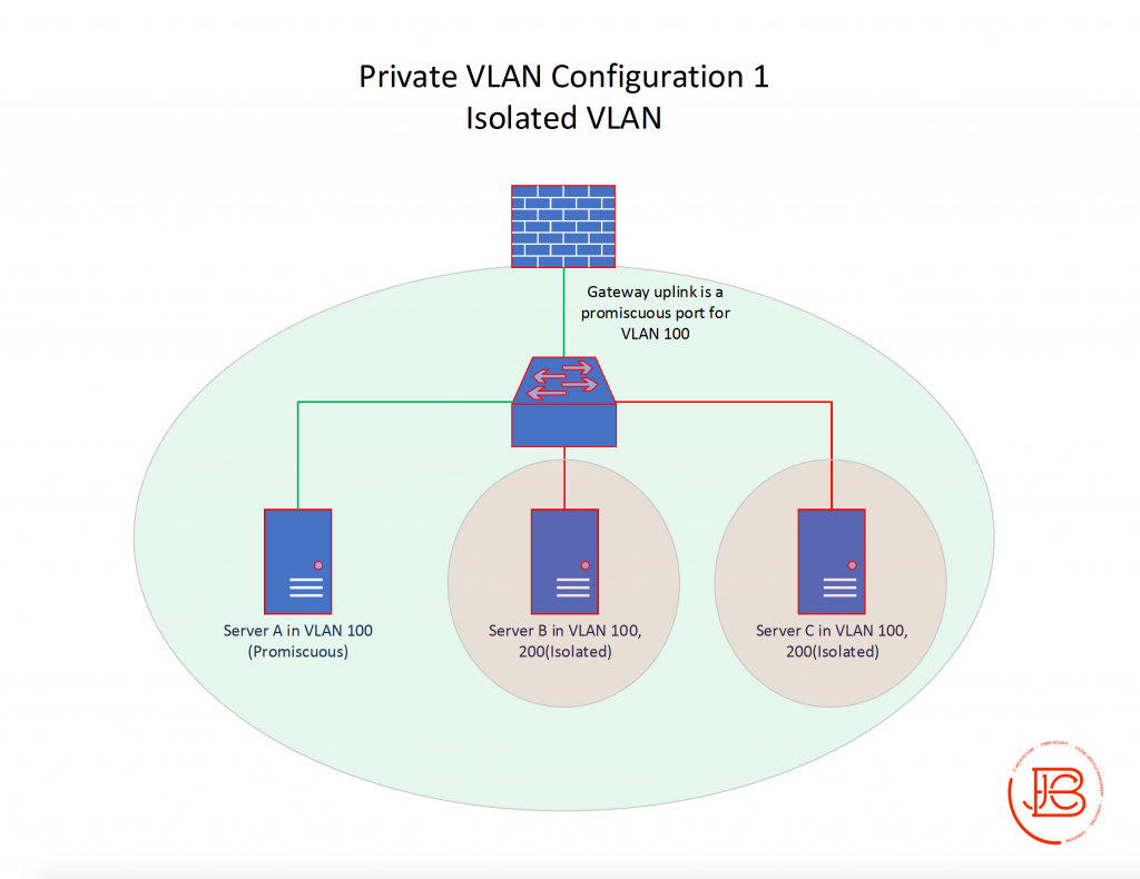
In this scenario, Server B and Server C can communicate with Server A and vice versa. However, Server B and Server C cannot communicate with each other. All servers can communicate with their gateway on the firewall.
Configuration 2 instead swaps out the isolated secondary VLAN and implements a secondary VLAN (VLAN 300) configured as community VLAN consisting of Server B and Server C.
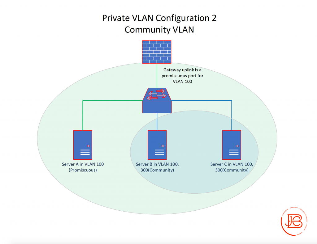
In this scenario, Server B and Server C can communicate with Server A and vice versa. Server B and Server C can also communicate with each other as they are part of the same community subdomain. All servers can communicate with their gateway on the firewall.
Configuration 3 takes the setup in configuration 2 and also adds back in the secondary VLAN (VLAN 200) which is configured as an isolated VLAN consisting of Server D.
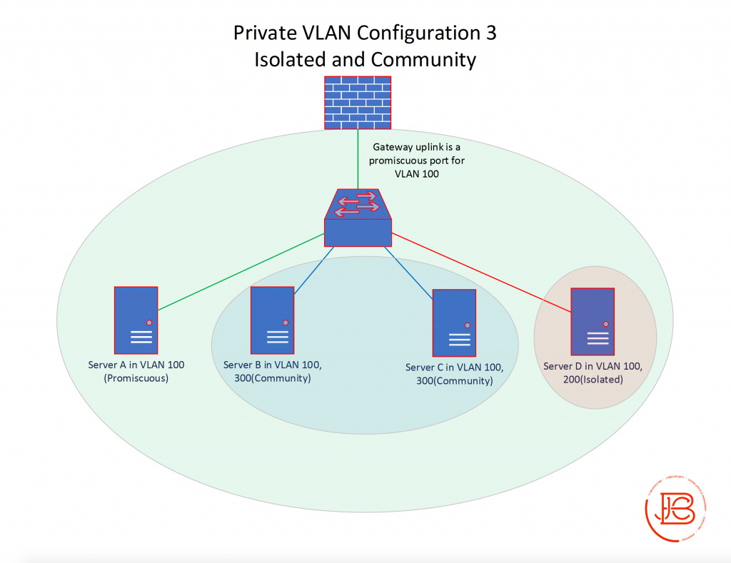
In this scenario, Server B, Server C, and Server D can communicate with Server A and vice versa. Server B and Server C can also communicate with each other as they are part of the same community subdomain. Server D can only communicate with Server A and the gateway. Server B and Server C cannot communicate with Server D or vice versa. All servers can communicate with their gateway on the firewall.
Lastly, Configuration 4 adds in a new secondary VLAN configured as a new community subdomain. This new community VLAN is VLAN 400, and consists of Server E and Server F.
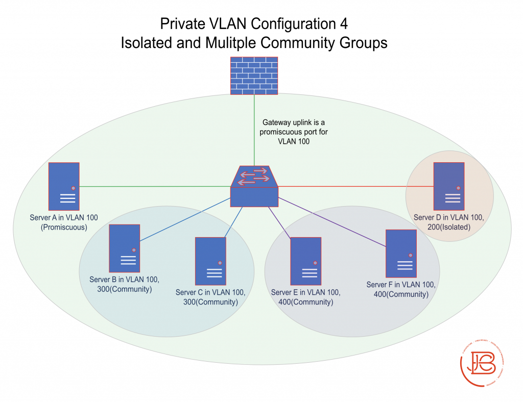
In this scenario, Server B, Server C, Server D, Server E, and Server F can communicate with Server A and vice versa. Server B and Server C can also communicate with each other as can Server E and Server F as they are part of the same community groups. The servers in VLAN 300 (Server B and Server C) cannot communicate with the servers in VLAN 400 (Server E and Server F) and vice versa. Server D can only communicate with Server A and the gateway. All servers can communicate with their gateway on the firewall.
My goal with the above information was to try to explain at a high level how PVLANs work. When implemented correctly with some strategy in regards to required data flows between systems, they can be used as an effective access control measure. Having an understanding of what devices really need to communicate with each other in your environment while implementing PVLANs (coupled with further network segmentation) can provide some stringent controls against lateral movement within an environment. In part two, I’m going to go a bit more in-depth into the configuration, use cases, and some interoperability concerns when implementing this PVLAN technology.
Some good resources on the topic of private VLANs:
- https://www.cisco.com/c/en/us/td/docs/switches/lan/catalyst6500/ios/15-2SY/config_guide/sup2T/15_2_sy_swcg_2T/pvlans.pdf
- https://tools.ietf.org/html/rfc5517
- https://www.juniper.net/documentation/en_US/junos/topics/topic-map/private-vlans.html
- https://www.cisco.com/c/en/us/td/docs/switches/datacenter/nexus9000/sw/7-x/layer2/configuration/guide/b_Cisco_Nexus_9000_Series_NX-OS_Layer_2_Switching_Configuration_Guide_7x/b_Cisco_Nexus_9000_Series_NX-OS_Layer_2_Switching_Configuration_Guide_7x_chapter_0110.pdf
Find out more about J.B.C.’s Cyber&Sight™ blog here.